Nintendo Switch Teardown
7 Min Read March 3, 2017
Nintendo’s wildly popular hybrid console, the Switch, gets the teardown treatment as TechInsights dives into the hardware powering its versatile gaming experience.
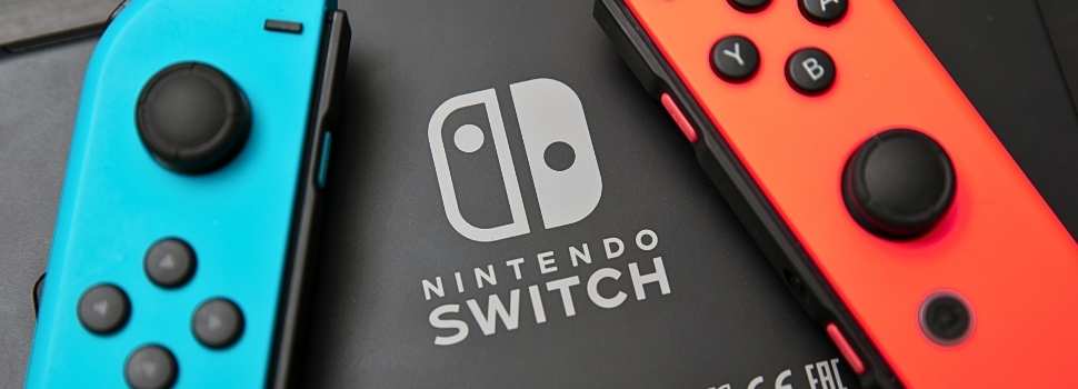
Friday was a big day for Nintendo, and indeed the gaming community as a whole, with the launch of the new and innovative console-tablet hybrid, the Nintendo Switch. For consumers lucky enough to get their hands on this new release over the weekend, tearing it apart is probably the very last thing on their minds. Here at TechInsights, however, we couldn’t wait to get started and take a look at what is bringing our heroes, Mario and Link, to life once again.
This unique combination of mobile play with big screen living room comfort in one integrated system gives us at least four different component parts to tear down and do what we do best. We were particularly eager to delve into the mystery of those Joy-Con controllers and see if we can provide some new insights. Be sure to read to through to the end to see what we discovered.
Nintendo Switch Main Console
We will begin our adventure with the main console unit. With the Joy-Con controllers attached in their slots on either side, this unit forms the mobile gaming system component of the Switch. It includes a touchscreen as well as the main PCB and components of the hybrid system.
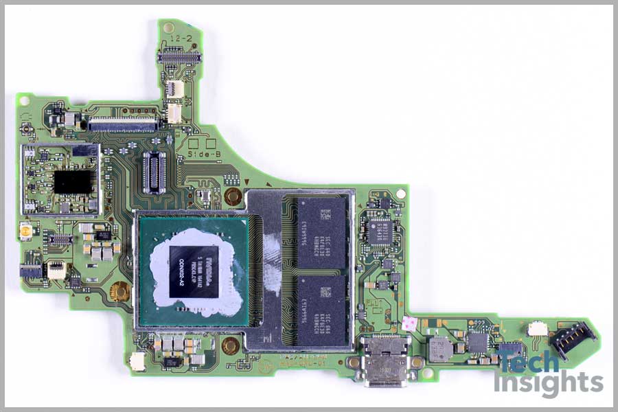
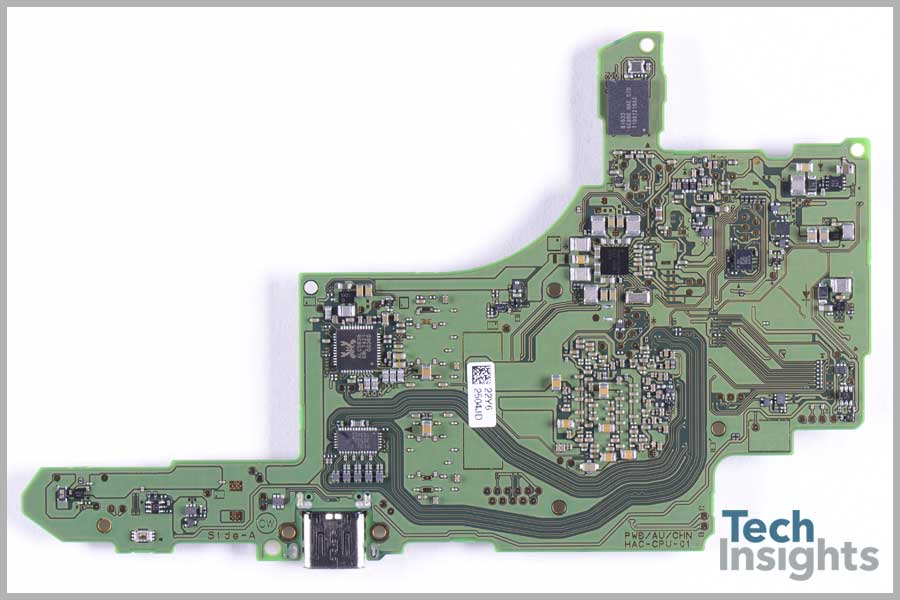
On this main PCB we found the expected NVIDIA ODNX02-A2 Tegra SoC as well as a Broadcom BCM4356 single-chip 5G Wi-Fi IEEE 802.11ac 2×2 MAC/baseband/radio with integrated Bluetooth 4.1, FM receiver, and wireless charging, a STMicroelectronics SH641 6-axis accelerometer and gyroscope ultra-low power MEMS inertial sensor, a Samsung K4F6E304HB-MGCH 16 Gb LPDDR4 SDRAM, and a Texas Instruments BQ24193 battery charger.
Update!
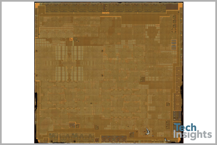
After subsequent processing of the GPU from the Nintendo Switch, we have determined that the processor is the Nvidia Tegra T210. The T210 CPU features 4 Cortex A57 and 4 Cortex A53 processor cores and the GPU is a GM20B Maxell core.
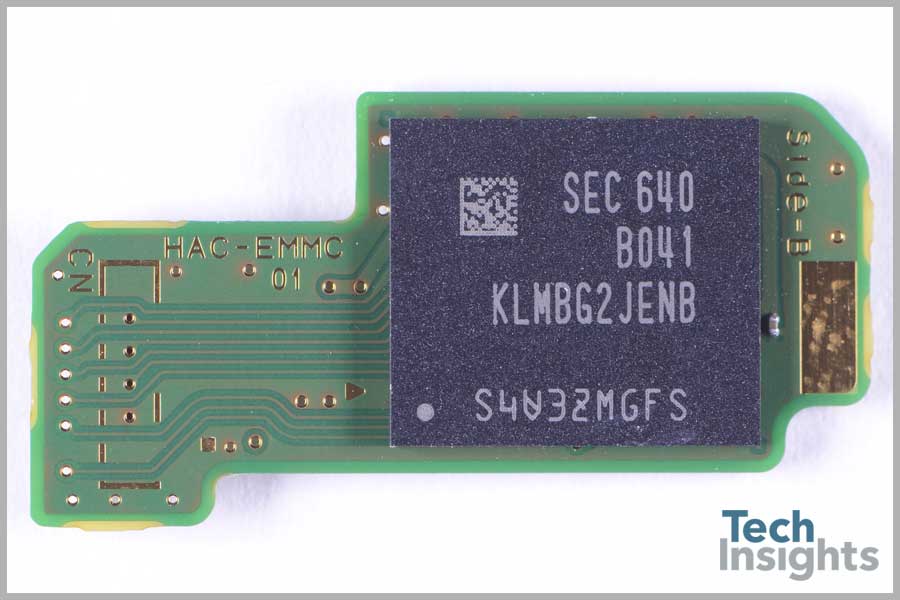
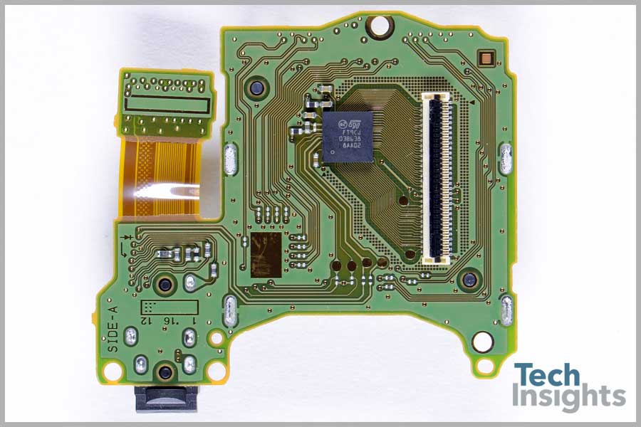
On a separate storage board was a Samsung KLMBG2JENB 32 GB eMMC. Interestingly, iFixit found a Toshiba THGBMHG8C2LBAIL 32 GB eMMC NAND Flash IC here. Does this independent storage board indicate plans for a future model update with expanded storage, as some have speculated, or is it simply to accommodate these variations in memory manufacturers?
The reverse side of the PCB included a Maxim MAX77621 DC/DC converter, a Realtek ALC5639 audio codec, and a Pericom PI3USB30532 USB 3.0/DP1.2 3:2 matrix switch.
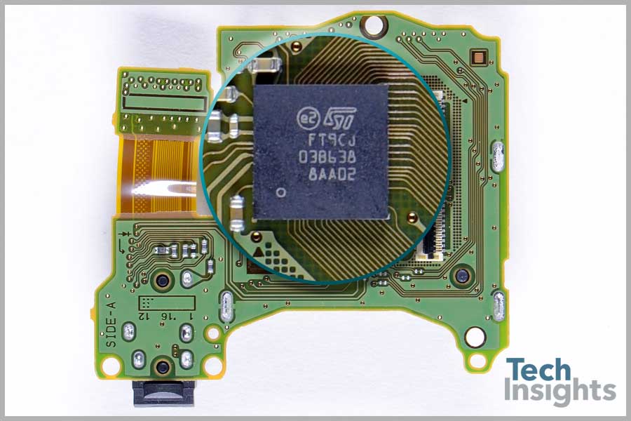
Also on a separate display board, we found the STMicroelectronics FT9CJ touchscreen controller. The FT9CJ is from the STM FingerTip multi-touch ultra-low power touchscreen controller product line. Based upon observations of the pinout and the flex connector, this touch solution may have up to 60 channels. This device is not on the STMicroelectronics website and must clearly be a unique design by STM for Nintendo.
STMicroelectronics has had great success with their touchscreen solutions in the mobile phone industry. In fact, they are branching out even further into automotive and industrial as described in this recent article.

Docking Station
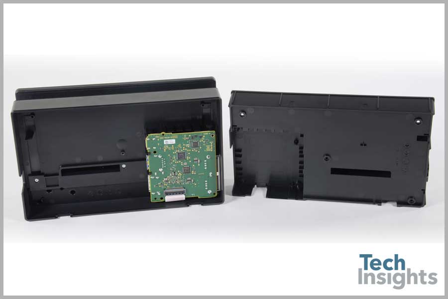
When the main mobile unit is placed into the docking station, the Switch morphs into its living room console counterpart, and brings your games to life on the big screen.
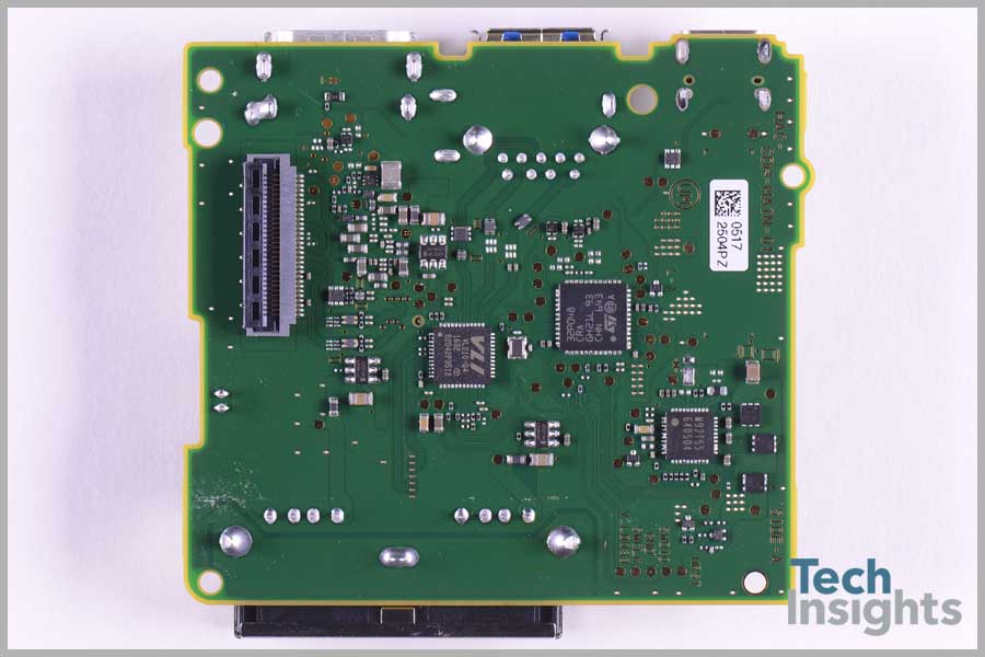
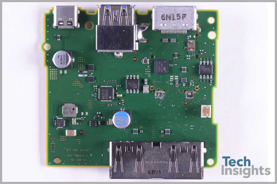
This additional functionality is brought to you by a VIA Labs VL210-Q4 USB 3.0 hub controller, a STMicroelectronics 32P048 (likely MCU), a Macronix MX25V2006E 2 Mb serial Flash and a MX25L512E 512 Kb serial Flash, a MegaChips STDP2550 Mobility DisplayPort (MyDP) to HDMI converter, a Texas Instruments TLV62130ARGT (“VUNI” package markings) DC/DC converter, and an unknown M92T55 chip.
Joy-Con Controllers
The surprising story of the early days of the Nintendo Switch is the Joy-Con controllers. Before we dig into the connectivity issues and their possible causes, let’s begin with what we know.
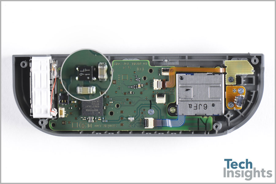
This device is the STMicroelectronics LD39020D low dropout regulator (LDO) that which features a very high power supply rejection ratio (PSRR) and a low quiescent current of 200 mA. This LDO is used in each controller and the docking station.
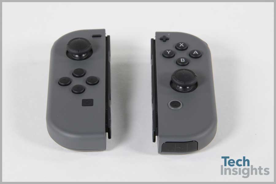
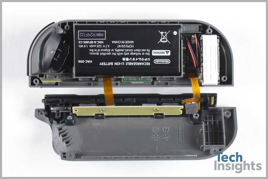
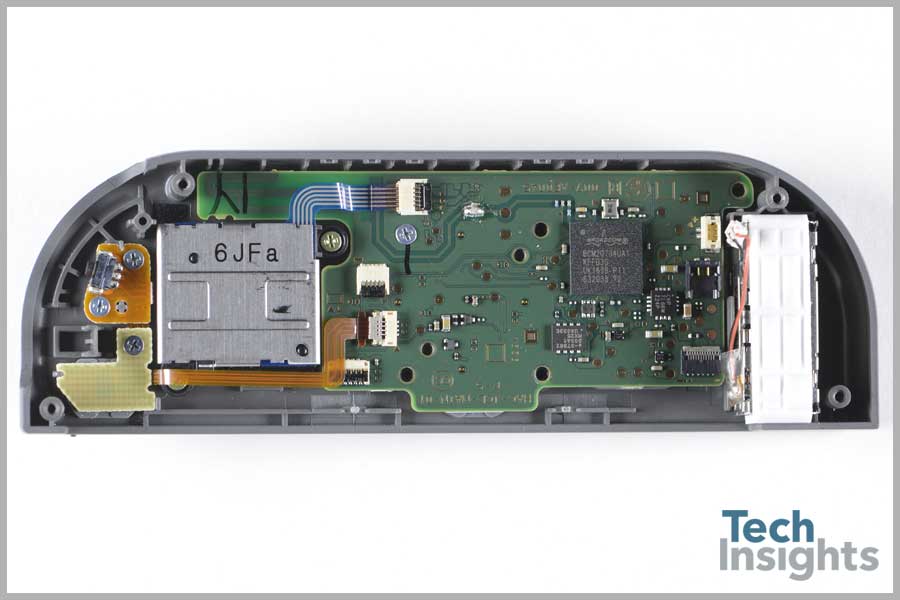
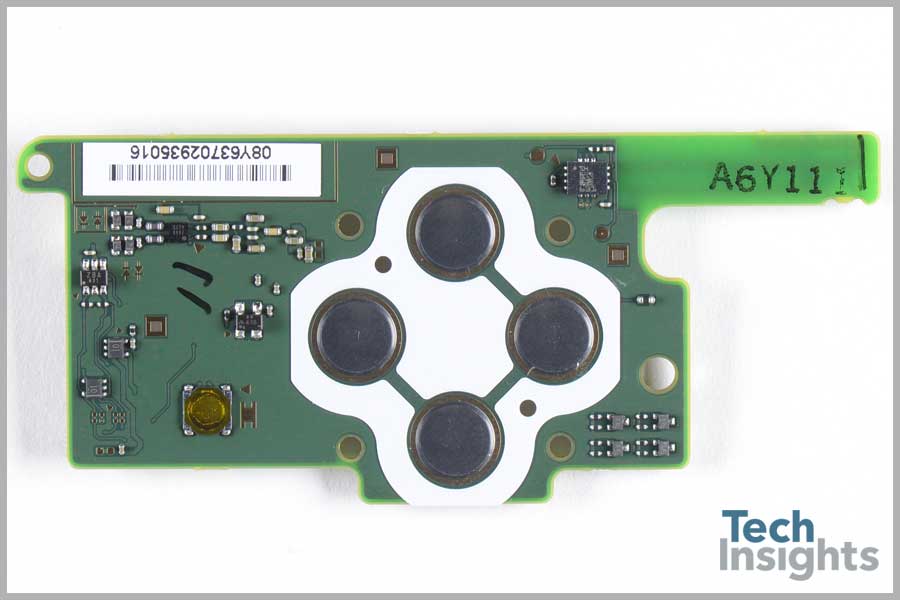
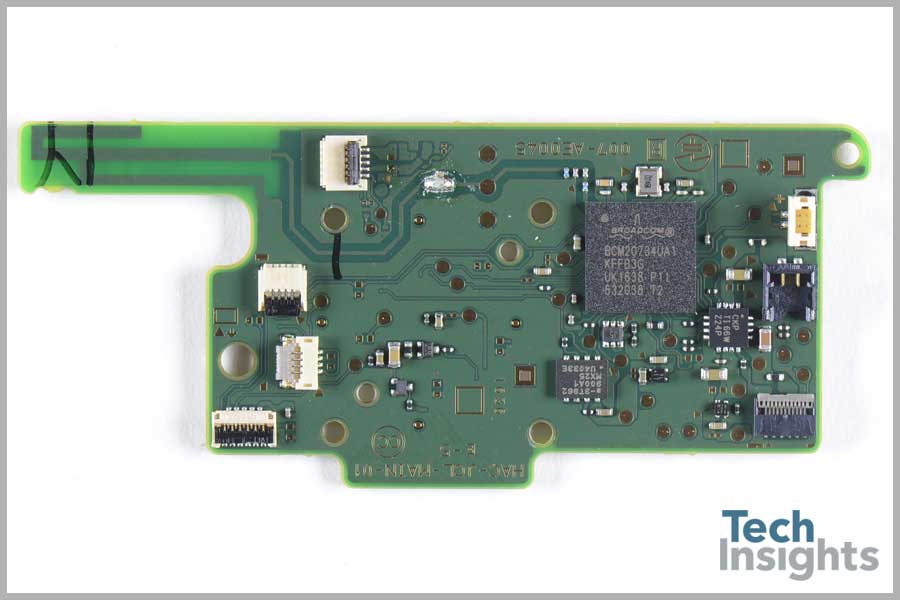
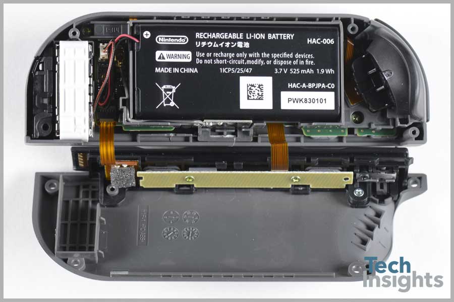
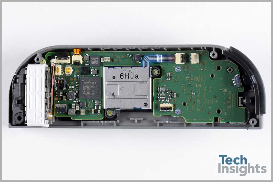
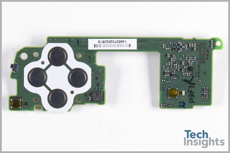
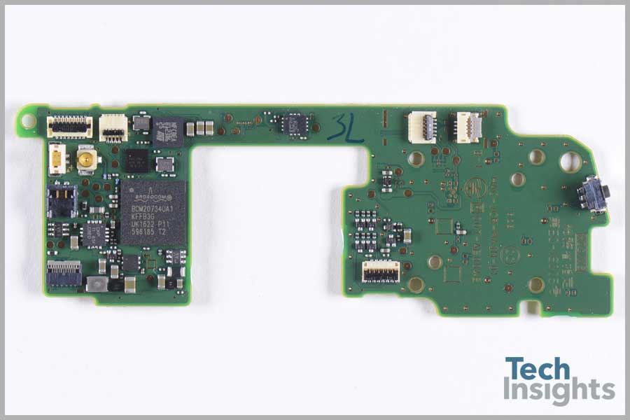
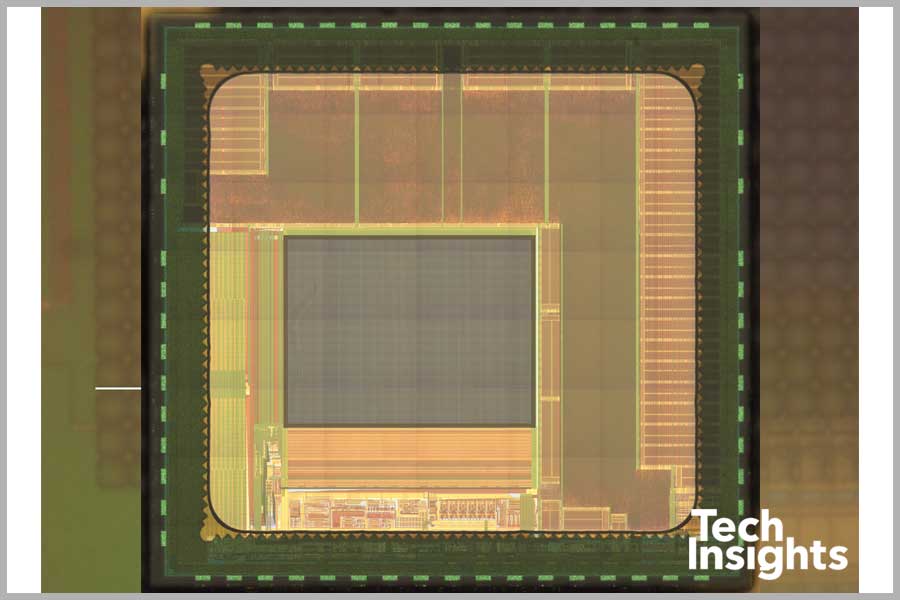
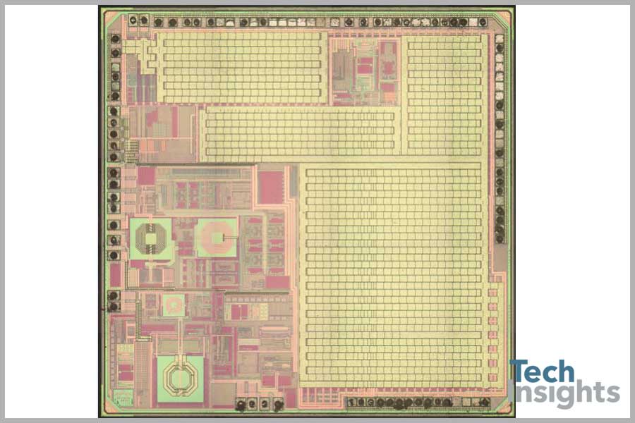
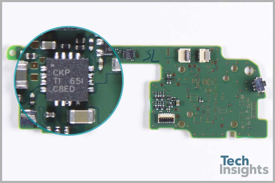
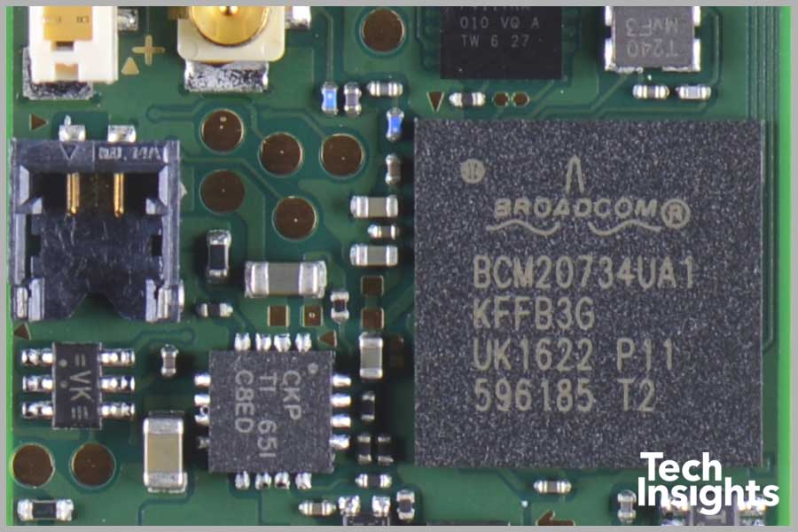
While different in functionality, and apparently performance, the left and right controllers share a few parts in common. These include a Macronix MX25U4033E 4 Mb serial CMOS XSMIO® (Serial Multi I/O) Flash memory, a Texas Instruments BQ24072 (“CKP” package markings) battery charger, a Broadcom BCM20734 Bluetooth transceiver, and a STMicroelectronics SH627 6-axis accelerometer and gyroscope ultra-low power MEMS inertial sensor, part of the LSM6DS3 family, a system-in-package featuring a 3D digital accelerometer and a 3D gyroscope. The Broadcom BCM20734 is of particular interest as it supplies the connectivity between the controllers and the main console, but more on that later. In the meantime, have a look at the BCM207xx top metal die photograph.
In addition, the right Joy-Con includes an STMicroelectronics NFCBEA B123D6 NFC IC, which provides the interface for the Amiibo figures that can be used to insert characters into the various games.
Joy-Con IR Camera Module
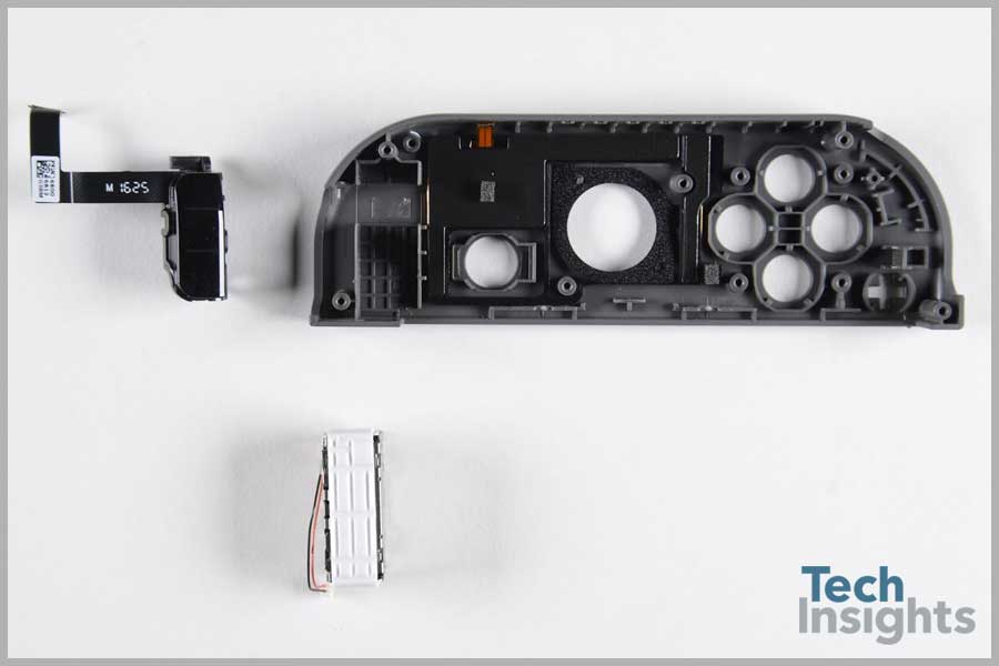
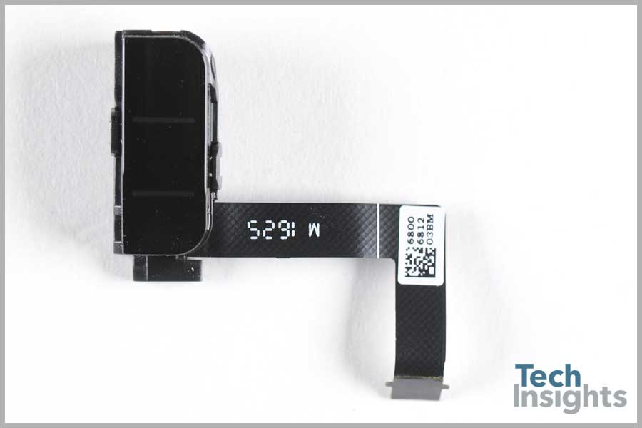
Also residing in the right Joy-Con is another feature, the motion IR camera. This camera is an infrared CMOS image sensor that is used to detect object shape and distance and, according to Ars Technica and Nintendo, will be able to record full video in the future. This camera sensor appears likely to be manufactured by OmniVision, and has a die size of 3.90 mm x 3.73 mm and a pixel pitch of 5 µm.
The Mystery of the Joy-Con Connectivity
Since the initial reviewer releases of the Nintendo Switch, there have been wide reports of intermittent connectivity challenges between the Joy-Con controller in handheld mode and the main console. Online videos show the player covering the controller with their other hand, or placing it behind their back, causing the controller signal to jump and sometimes disappear altogether. These problems were first noticed in reviewer units causing concern among consumers. While the issue is not consistently replicated in all units (or even with both controllers), they persist in newer consoles, even after installing a software update reported to solve the problem.
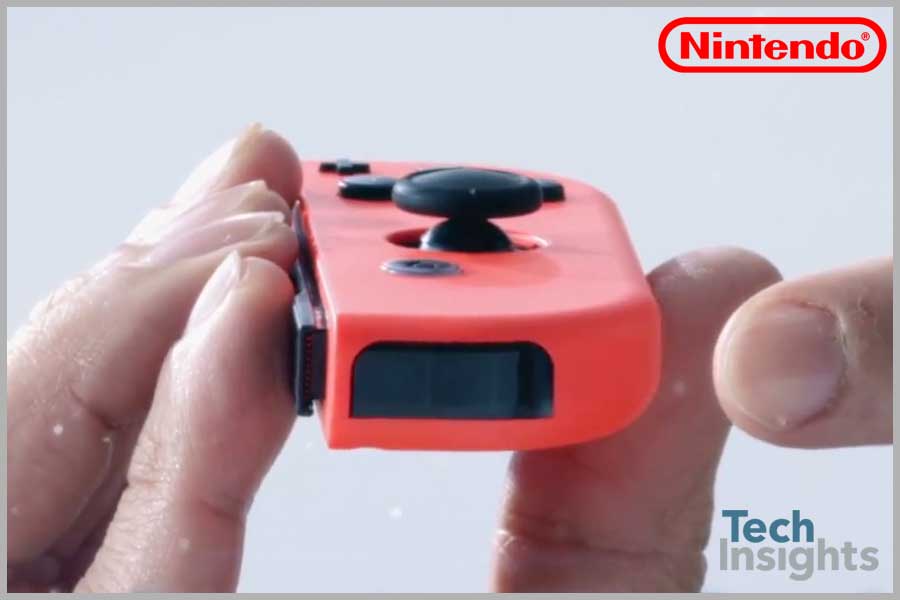
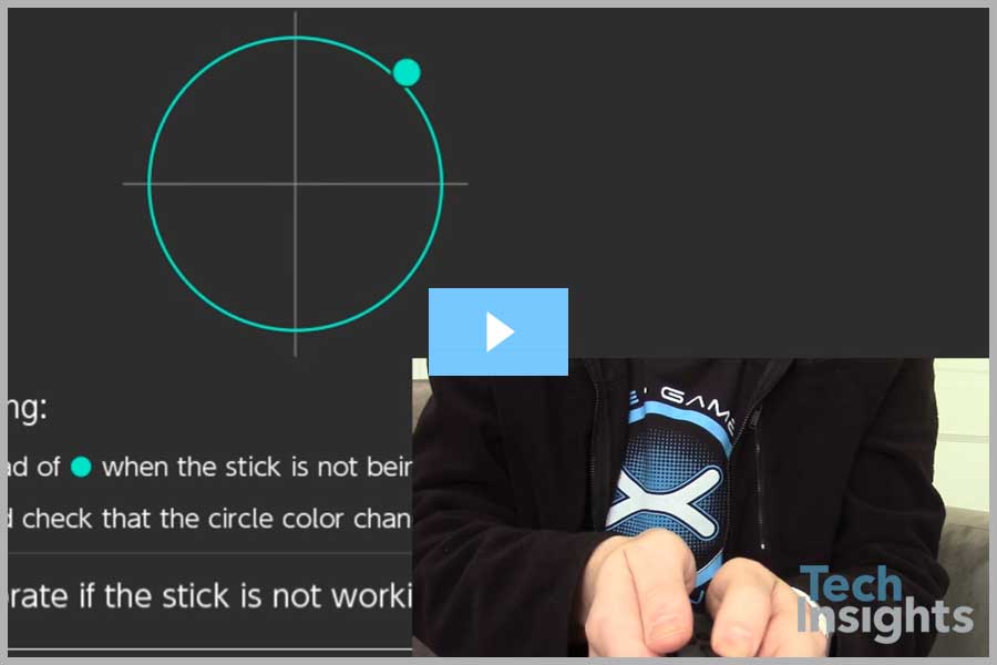
In this screen capture from the video linked above the player has moved his right hand to cover up the “inside” of the Joy-Con. On that inside surface, just under the plastic cover, is the antenna for the BCM20734 Bluetooth 4.1 SoC.
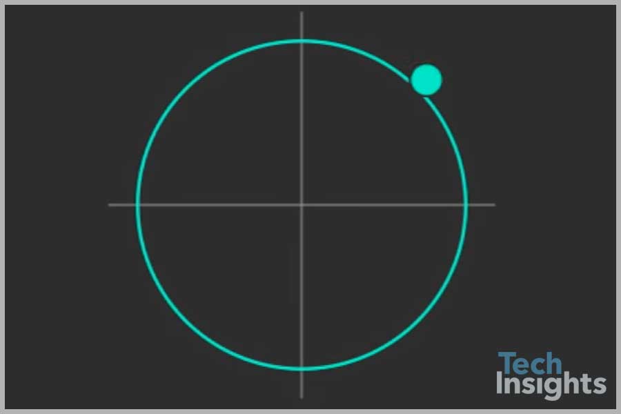
Is this syncing problem simply from covering the antenna or is there something more happening here?
On Nintendo’s support site they suggest interference from other BT transmitters may interfere with the Joy-Con signals, stating that “in most cases it will be enough to move these devices three to four feet away from the Nintendo Switch console and/or Joy-Con controllers. However, if you continue to experience this issue, please power these devices off while using the Nintendo Switch console.” Not only are reports of its efficacy mixed, this is really an impractical solution. How many game systems are in a room where there are other BT devices functioning? These days, probably all of them.
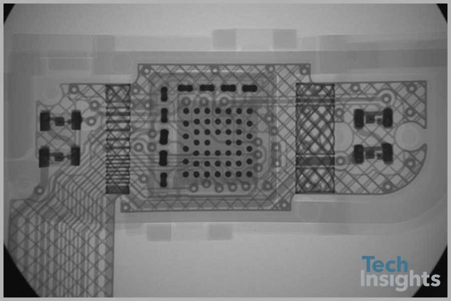
Unfortunately, we were too eager to begin our teardown to test our unit first, so we’re not sure if we got a good one or not, but it is possible that there is simply a bad design out there. In our right Joy-Con, pictured below, we see a pretty bare bones BT antenna design: a connector, a wire and a very small antenna. Perhaps the antenna is just too small.
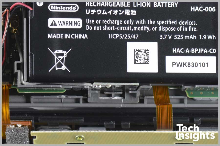
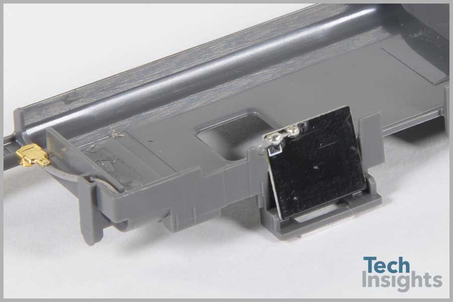
Here in a cleaner image, the antenna connection of the right controller can be seen more clearly. The gold connector on the left leads to a rectangular piece of fiberglass, or FR4, with a metallic coating that is the actual antenna. This rectangular plate resides on the flat edge of the Joy-Con and is underneath that flat face plate.
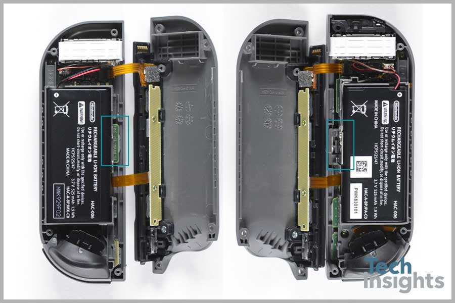
According to recent reports, the left controller does not share this design and instead “the antenna in the left Joy-Con is soldered directly onto the motherboard, right next to a metal box.” In the side-by-side image below, it can be seen that there is indeed no antenna in this location in the left controller. This points to a possible explanation for the more frequent issues experienced with the left controller.
Nintendo has been slow to respond to these reports. Their answer, when we get one, will be telling. Will they issue another software update that will more reliably fix it? Or will consumers with “faulty” units be offered replacements or repairs, pointing to a design flaw? We will certainly be watching to see what they do next.
Unlock full access to the Nintendo Switch teardown and discover the technology behind one of the world's most iconic gaming consoles—only on the TechInsights Platform.
(Subscription Required)


